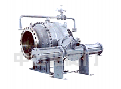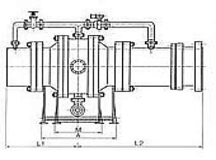
Note: parameters are for reference only, or are not full. Valve can be used in accordance with the requirements of different pressure, material, diameter, drive, etc.. Specific please contact or online advisory contact.
Adopt the piston stop water ring structure of double seal ring, it can be divided into upstream repair seal and downstream working seal. The sealing ring is arranged in the upstream and downstream sealing positions of the ring spool, and the piston stop ring is pressed to achieve sealing through the hydraulic system. When the ball valve is normally closed, the downstream working seal is closed to stop water smoothly, while when the downstream working seal is repaired or replaced, the upstream maintenance seal is closed and locked by the mechanical locking device.
The operating mechanism is a hydraulic operating mechanism (straight cylinder relay), and the straight cylinder relay is a piston-fork mechanism, which is equipped with a manual locking device, a signal indicating device for the position of the main valve and a signal indicating device for manual ingot input or release. Manual locking device can withstand the operating pressure of the relay, to avoid valve misoperation.
On the upper and downstream sealing ring of the ball valve, the position trip switch is set respectively. After connecting to the central control room through the circuit, the state of the sealing ring can be accurately understood, so as to operate the relayer on and off valve accurately.
The upstream of the hydraulic ball valve (main valve) is welded to the inlet pipe through the front short pipe of the valve, and the downstream is connected to the turbine volute through the expansion joint, so as to facilitate the installation and maintenance of the hydraulic ball valve (main valve) and the expansion joint adjustment.
The hydraulic ball valve (main valve) is provided with a bypass production pipeline, whose purpose is to balance the pressure at the upper and lower ends of the valve before opening the main valve, and reduce the opening and closing torque of the main valve. The by-pass valve is a hydraulic ball valve, and a manual valve is set before the hydraulic ball valve to check and repair the by-pass hydraulic ball valve.
The wedge gate valve of DN80 is arranged on the top of the telescopic joint. When the pressure steel pipe is filling water to the downstream turbine, the valve is fully open to remove air from the water surface. The manual gate valve with DN80mm and pn4.0mpa is arranged at the bottom of the ball valve and the telescopic joint degree, which is used for fully removing the dirt in the body cavity of the valve and the water in the volute during maintenance of the water turbine.
Two throttle valves are set at the two oil inlet ports of the switch of the relay, so that the opening and closing time of the valve can be adjusted according to customer requirements.
2、检验和试验按 JB/T9092 的规定
3、法兰尺寸按 JB79 的规定
4、结构长度按 GB12221的规定


